Monday, May 22, 2017

2017/05/17 - Final Post

As my time for ME 195 is will conclude at Wednesday May 24, this post will include everything from the previous post onwards.

On Friday 19th, my group successfully finished our presentation, and had a chance to showcase the T-Support model with the 12th scale bogie to the other students and staff. I had to leave shortly afterward as my brother was graduating the following day.

Following this I worked on the final paper, Specifically the "Table of contents", "list of figures", "Description of your design" "Analysis/Validation/Testing" and "Procedure/Instruction Manual," as well as general formatting. This took much longer to do than I expected as I always found something else that I needed to add, but eventually I put the finishing touches in the early hours of Saturday May 20.

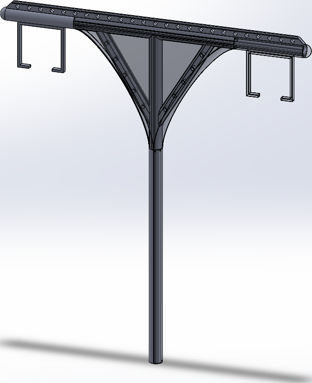
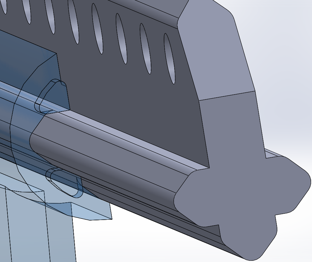
Of course, there was one more event: Maker Faire. My group had our own booth where we showcased and explained our models including the newly finished full scale stub from Vander-Bend! I assisted there for all of Friday and Saturday but could not attend Sunday. In addition, The 12th scaled group also gave us another spare bogie with a 3D printed podcar for the T-support model, was  super cool and really nice of them!


However, there is still one thing I need to finish. Although I have almost finished sorting my files from throughout the Spring semester, there were some errors in my SOLIDWORKS files (most importantly one of the laser cutter patterns and to a lesser degree the main assembly) that I would like to fix before I upload, in the chance a future group intends to refer to them. Due to my final exams on the 23rd, I intend to complete this on the 24th, which will still be before graduation.

In any case, I would like to thank everyone on the Spartan Superway for all of their hard work and support this past year: Dr. Furman, Ron, and Eric for letting me on the team and giving us guidance, my team for their hard work, the 12th scale group for the two bogies, and everyone for being so friendly and welcoming. In addition, I would like to also thank Dr. Youssefi for the 3D printed parts, Mr. Meininger for the laser cut parts, and my dad for helping me with the PVC and wood components. Finally, I would also like to thank our South African contact for lending us their information about the X-beams, and Vander-Bend for creating our Stub.

Saturday, May 13, 2017

2017/05/10 - The finished model and the following presentation

Please note that this blog post covers up to the day of presentation (May 12) as the two tasks were worked throughout the whole week.

The first task this week was finishing the model - which unfortunately had some unforeseen challenges. I realized on Sunday that while putting the components together, I had made a few errors in one of my laser cutter patterns - specifically, there were some missing holes in four parts and four less small parts than I needed. On Monday, we fixed the four parts with the missing holes: my dad and I simply used some of the other parts with the correct hole position as reference, and drilled the holes in the manner shown in the image below, and the results worked perfectly. We also made many wooden spacers for the upper part of the guideways, which needed to clear the support beam while looking relatively flush with the upper parts of the side brackets.


Likewise, the flanges that a teammate passed to me were unfortunately not the right type - having a threading where the PVC was supposed to go, and the holes for screws being far too big. For the first part, the solution was to purchase some adapters (two for me and one for my groupmate), which had the added advantage of allowing fine tuning for the pvc pipes height. For the second problem we simply drilled small holes into the thick areas off the flange, and by using a guideway as a spacing reference, attached them to a large wood board.

For the four missing pieces, I brought back the corresponding acrylic sheet on Monday and asked Mr. Meininger if he could make them, and he said yes. I obtained them on Wednesday, and brought them home and with them managed to put the finishing touches on the model, allowing me to bring it for the Friday presentation. I am very happy with the way the final assembly turned out, which is shown below (note the 12th scale bogie in a guideway):

The second task was working on the presentation. Starting on Wednesday morning, my group and I met together and collaborated on the google presentation. My main focus was on finding images of the different prototypes, SOLIDWORKS assemblies and elements of documents from our contact. to explain what we had learned and build through the year. I also made major contributions to improve and fill out the bill of materials, adding my purchases and significantly cleaned up its format. Lastly, I did some general format checking, and some small slide rearrangements to improve logical flow.


Wednesday, May 3, 2017

2017/05/03 - Approaching Completion

On Thursday, used a file on the 3d printed clamps to remove protruding elements and also to try making the internal surface a little flatter.

On Saturday, I finalized the SOLIDWORKS file to have a visual display of the final assembly (figures 1 and 2). While doing so, I realized that I had made two small mistakes with the guideway: I had misplaced a few holes in  the for the guide for the parts towards the end of the assembly, and I had not left any clearance for the flat ends of the guideway. These were simple fixes however, and I sent the new version to  Kyle Meininger with no problems.

Figure 1: the final assembly
Figure 2: the Guide way (with hidden parts for visibility 
- note the altering parts on the upper portion and the "T-shaped" wooden spacers)

On Monday Mr. Meininger and I went to the ME 101 laser cutter (the one in figure 3), where he cut the parts for me. I was there for the first batch of parts and managed to pack them up, but I had to leave for class before the second set was complete, but I will be able to pick them up before the last class. 

Figure 3

Figure 3 and 4 The first batch of laser cut parts.

When I got home I tested my new parts with the 3d printed clamps and the wood beams, as you can see in figure 5 the parts fit perfectly together (though a small washer between a clamp and the acrylic parts to prevent wobbling).

Figure 5: a successful assembly

Now, there are a few things left for me to do: with my dad, cut parts of the PVC pipe for the covers, and the ten wood parts for guideway, put blue tape on the 3d printed parts and clean the acrylic parts


Tuesday, May 2, 2017

2017/04/26 - Back on Track

This week I was centered around the 3D-Printed parts and the laser cut patterns.

As the previous week's 3D printed parts had the right dimensions, I just remailed Dr Yoseffi with the last set of part files. Specifically, there asked for 1 cap, 1 pair of vertical clamps, and 3 pairs of horizontal clamps. As he didn't answer, I was worried that the email didn't reach him - but when I talked to him on Wednesday, he already had them finished!

For the Laser Cutter, I spent a lot of time completely remaking the pattern for two sheets. Although this game me a lot more room to place parts, it brought in a lot of challenges due to the required spacing between parts and the laser kerf (diameter). Specifically, I was advised that the minimum spacing required would be 1/8 of an inch and that the laser was between 20 and 25 thousandths of an inch - as such, I made the spacing be 3/16th of an inch and the offset (to compensate for the kerf be 0.02 inch). I realized that the guideway's 6,12 and 18 parts and the required 3 clamps would no longer fit well onto the sheet pattern (leading to a lot of wasted acrylic), so I modified them to be 5, 10 and 15 parts (which would require one more clamp). Despite this, I still had to try different configurations to minimize waste. After a lot of trial and error, I managed to find a configuration that would also allow me to design a new type of clamp that would allow me to attach the upper guide way parts directly to the PVC pipes. Also, I designed an easier way to keep the two sided spaced equally (more on that next week's blog post though).

Figure 1: The old part assembly

 Figure 2: the new support and clamp part pattern

Figure 3: the new guide way part pattern

Wednesday, April 19, 2017

2017/04/19 - Good News, Bad News

This week has had a lot of positive advancements, but a lot of setbacks as well.

After last Wednesday's class, I met Mr Youseffi to pick up the small clamps. In order to try counteracting the x-y decalibration, we tried a newer 3d printer. We also oriented them in different ways to see if any orientation would work better (ie x vs y axis orientation and flat side up vs flat side down) to see if it would make any difference. When I measured them at home I found that the dimensions along the flat surface was the perfect 1.05", meaning that the x and y servos were in perfect order. however, along the z axis the combined clamps had a total distance of 1.08", making for a difference of 0.03". Although I was planning on filing the 1.05" diameter a little to let it fit smoothly into the PVC pipe, when I tried to do so with this 1.08 effective diameter I realized that going through the extra 0.03 inches with my hand file was making the surface excessively distorted and uneven. Nonetheless, I made a revision to all of the clamp parts by changing the 1.05" diameters to 1" with the idea that with the smaller size, I could just warp it with blue tape until it can fit snugly into the pipe. Finally, I sent Dr Youseffi these new versions, and hopefully I will have the results today.
The clamps were not the only thing I worked on today. Over the weekend, I worked on dramatically refining my laser cut acrylic pieces and patterns. for starters, I completely removed the 1 piece 2D brackets and the complicated connection system. For this new version, I made it so that the brackets would be composed of  1"x4.5" and 1"x.75" rectangles with holes for screws, Rails for the 1/12 scale car with a cross sections of 0.25"x1.5" and two sets altering 0.25"x0.5" upper support beams, all of which would also use the screw system. The assembly would look something like the blue lines image shown below (which is super imposed over the 1/12 scales groups's existing bracket. However, I will need to devise a way to connect it to pvc pipes and make the upper portion of my braket (keeping the two support beams spaced evenly. In addition, I've also included my current draft for the laser cuttout pattern.
Sadly, my progress with the laser cutter was not as productive. On Monday I was informed that due to a conflict with the laser cutter's driver and modern Windows, the computer that was supposed to be dedicated to the the laser cutter no longer works and so I re downloaded the drivers for it. On Tuesday, I spent two hours attempting to get the lab laser cutter to work with my laptop, but it was a complete failure. As such I contacted Dr. Barez about his departments, laser cutter, who told me that I should contact Dr. Obi, who also told me to contact Mr. Peters and Mr. Meininger.


2017/04/12 - Wood, Acrylic, and ABS


This week, I had three main focuses: milling the wood bars to have the triangular slits, refining the acrylic brackets and guide-way as well as manufacturing the smaller horizontal and vertical clamps. Although the first one went perfectly, the other two did not go quite as smoothly as desired.

My dad and I, milled the wood sections went perfectly well. We made 1/4" by 1/2" triangles on a 1"x1"  wood bar and a 1/8" by 1/16" triangles for multiple 5/8"x5/8" wood pieces using a 45 degree router bit. In addition, we also used a 1/16" radius router bit to round the corners on the 5/8"x5/8" router bits so they can better fit into the clamps.

Figure 1

For the acrylic parts, I realized that the sample bogie would not be able to clear the PVC pipe as shown below in Figure 2, and so I attempted to redesign the connector parts  so that it would hold the support beams from above instead of from the center, and it would have offset edges allowing for altering connections (Figure 3)- however these alternating connections would likely be too weak and needlessly complicated. In addition, the bracket itself would also bring problems - the way it is only made in a 2D plane would make connections to both the support beams and bogie rails be too difficult as well, and the cutout area takes up too much space.

Figure 2

Figure 3

For the 3d printed parts, the problems were in the the dimensions of the smaller diameters (where the pvc pipe would connect. In my first T-clamp print I noticed that the  between the nominal diameter (of 1.05 inches) and the effective diameters of 1 in on the vertical and 1.06 on the horizontal sections. On the second version, I realized that the measurements of these were inversed. I presume that the reason why is that the two iterations of clamps were oriented 90 degrees from each other, and one the x-y servos must be decalibrated. In any case, I used my default dimensions for the small clamps shown in figures 4 and 5.

Figure 4 and 5


Wednesday, April 5, 2017

2017/04/05 (and 2017/07/29) - Physical Models and Refinments

During the last two weeks, I did a variety of things for the super way project.

The first thing was to mill the 2x2" wood into 5/8x5/8" and 1x1" pieces. With this and a segment on 1" schedule 40 pvc pipe, I could properly test the existing pair of clamps. With some sanding on the corners, the 5/8x5/8" wood fit perfectly, but there was some issue with fitting the pvc pipe on the horizontal part of the clamp.

 IMG_20170404_173839982.jpg
Next, I refined the design of my clamps. Specifically, I modified a several of the length dimensions, and then added flaps to the bottom of the T clamp while pushing them out by 1/8 of the edge, which would allows laser cut acrylic parts to be placed within. I also changed the diameter of the horizontal parts of the clamp so the next model would be able to accept pvc pipes without filing it down. Finaly, I merged the different types of clamps into one Soldworks document (by using the suppress feature to allow changes between the different types of clamps), so that making modifications would be a lot faster and simpler.


Likewise I made a first draft template for the laser cut part. The acrylic sheet will be used for many different types of parts, such as the trusses, the upper horizontal support beam (which will allow additional modifications such as for the solar array), the guide way connecters and beams as well as the brackets (based on those made by the 12th scale group). Though not yet designed, it will also be used to make the guideway rails. 


The end result for one of the two support columns will look like the picture below, , though there still will need to be significant modifications to the guide way parts
Finaly, I also worked on the presentation for today. In addition, I also should mention important to mention that I did an essay for ME 195B on the Three Gorges Dam and its societal and cultural effects.

Wednesday, March 22, 2017

2017/03/22 - Preping for Production

This week I refined the 3D print clamp design so that it will be made from smaller components, as well as some other refinements. For one, the areas where the PVC rested used to be composed of seperate quarter smaller parts, which I simplified into a solid (half) circle that can be modifed in size to fit the PVC pipe covers. In addition, I removed the triangular segments that would go into the corresponding cleft, as this simplifies fitting and manufacture.


The image below will give and idea what the assembly will look like. The brown parts are the wooden cross beams, the white segments are the pvc pipes covers (which will go over the rest of the wood sections-not just the area shown), the round grey segments are the 3d Printed parts, and the floating parts are Erector parts that will represent the guide way supports (though I still have to design a way to connect it). Likewise, I intend to use other Erector parts to represent I beam that will be how the clamps will connect each other (which will be placed on the clamps' flange holes), but they are more difficult to replicate.

In addition, I contacted Dr. Youssefi to see if he could print out one or two of the clamps as a reference. Fortunately, He managed to manufacture them shortly after.


During spring break, I will make a few of the components (ex. the wooden beams) and further improve on my design (ex. a way to connect the guideway supports). I will also have to consider designing parts to substitute the erector parts if I can't obtain them in time.


Thursday, March 16, 2017

2017/03/15 - Clamping Down on a Design

This week I attempted to finalize the design and dimensions for our architect's model.

Firstly, I decided that we should make our design be 1/12 scale as it the long nature of the structure would make the parts require far too much material.

Then, I made the cross-sectional dimensions of the wooden beams, followed by the dimensions that the attached clamps will have. I also looked into using erector parts which would represent I beams and the modular solar rack base. The basic design is shown below, with the 3d printed and erector parts being highlighted blue. In addition, for large portions, pvc pipes will be used as sleeves to show a smooth look and potentially additional support.


Next was designing the clamp itself. This is one solid part, but as pointed out by a teammate it is too large to be reasonably printed (being over 10 inches long).


Currently, I am redesigning the clamp to be composed of multiple smaller pieces, while still taking advantage of the core idea. Likewise, I will need to find an easy way to attach the guide way.

Wednesday, March 15, 2017

2017/03/08 - Skype around the World

This week, There were two main events:

On Wednesday night, I participated in a skype call with Ron Swenson, Kathlyn Garces, and Andries Louw (who was in South Africa). I shared my documents and designs and we further discussed these and other aspects very thoroughly. Also, Andries showed us a new support structure design, and we intend to see if we can use it.

The other event was an essay for the ME 195 course. The whole prompt was based on the project, and how applying challenges applying it to other countries. Unfortunately, researching and writing for it took up a lot of my time, preventing me from progressing on the project itself.

In addition, I tried seeing if I could refine my project to facilitate production as the maker fair event is coming up soon. This turned out to be more complicated then I expected, so will to discus this further with my groupmates

Wednesday, March 1, 2017

2017/03/01 - The First Spring Presentation


This week, my primary objective was to work on the "Current Status of Design" portion of the presentation. For it I recompiled the different designs our group made through the semester, including the original sketches, the "cat's eye" design, and the sleeve/clamp configuration, and will also talk about the potential solar panels.

In addition, I also made a newer version of the sleeve/clamp design: it uses a "truss clamp" to save weight, an extruded upper segment for the horizontal beam with holes in it that can allow for modular attachments, and cleaner sleeves.

It is also important to mention that I also went to the meeting with Eric Rosenfeld on Saturday. There he explained his research for solar panels (most notably the snap rack system) and we in turn explained our potential designs. We brainstormed about ways to attach the panels, and I suggested using a series of altering cables to hold up the panels, which he seemed to like.

Sleeves.png

2D Outline of Truss Clamp Design

3D Representation of Truss Clamp (with upper guide way beam supports)

Clamp Assembly.png
Semi Translucent Representation of Truss Clamp (with full guide way brackets)


Close up of the Clamp Connection (note the triangular segments to hold adjacent sleeves)

Tuesday, February 21, 2017

2017/02/22 - A New Consideration

During the last session, we learned that we would need to integrate Solar panels into our design as a large "full roof" canopy similar to the one shown below.


Before this, I had assumed that the Solar panels would have been installed directly above the guide ways, which will make a significant change in my assumptions (requiring the final design to also be able to hold perpendicular support beams in addition to the guide way and pod cars).

We were told to contact Eric Rosenfeld about the solar panel mountings, and he gave me his report from last semester. Also, I tried emailing my other group members for the meeting, but only one responded, so I will have to confirm with them tomorrow.

Lastly, I made a new design to try to get it closer to the original palm tree design:
This design features a horizontal x-beam in addition to the standard vertical one. It uses a series of sleeves to give it a smooth look and has a version of my 3 part clamp to fix the beams. The portions sticking on top is meant to have a series of holes that can be used to fix modular mountings (similar to mechano/erector toys) in the most effective way for the solar panel at any given location. I have difficulty integrating the triangular central hole though, as it will ether be too small to notice or interfere with the strength of the whole system

That being said, I suspect that the "cat's eye" design would work better if the solar canopy is in a curved shape (as in the photo, but the T would also work well if the canopy is meant to self adjust or if it is a flat array. In any case, I find it a little odd that we were asked originally to try to make the palm tree design as it will be hidden by the full roof canopy and will look very different from the example that the client saw.

I also want to note that I reattempted to contact Andries, during the February 15 meeting, but he has not yet responed.

Tuesday, February 14, 2017

2017/02/15 - Sketches and Designs

The first task I did for this week was writing an email to Andries asking if he could make a blueprint for the Stub column that Vanderbend could manufacture for us (using 1/8 inch sheet metal and some approximate external dimensions). He hasn't answered yet, so I may need to retry to contact him this week.

Like wise, we were tasked with designing the support structures. I made some rough sketches in the class section about a potential clamp design (involving one upper and two side parts - show at the lower left) and support configurations. Of the support designs, the most interesting one made would be the have to be the one in the sketch at the lower right. The way it works is that at the top, one beam or simple CFT (concrete filled tube) is held at the top of the column (preventing vertical motion), while there are two beams/CFTs that each an rest one end on opposite vertical sides of the column (preventing horizontal motion). The upper beam/CFT and the lower beams/CFTs would be able distribute the load among each other, while also using their weights to create a squeezing effect on the Column, allowing them to remain firmly attached without need of making holes (and consequently weak points) in the column, though they still require a would a system of custom clamps.


Later in the week I made some accurately scaled variations of it in SOLIDWORKS,
which can be seen below. If any of the designs are selected, I will work next week to design some clamping mechanisms would be compatible with it.


Tuesday, February 7, 2017

2017/02/08 - New Objectives

This week I focused mainly on gathering information about how our group should proceed for the spring semester.

I had written down many questions to ask Andries about his x-beam design before meeting meeting, and he did answer most of them and pointed out several features not explicitly shown in the blueprints.

Afterwards I discussed with my group-mates and with Mr. Swenson and Dr. Furman about what we should do for the deliverable. Although my group and I were originally expecting to do a medium T-shaped prototype, we later learned that a clients wants to build a round and curved Y-shaped version. In addition Andries said that we should actually do a smaller model to showcase the final look (similar to an architect's model) with working cars and a full scale column "stub" to show the technology behind it. This changes the plan dramatically, but likely will make things a lot simpler for our group.

At home, I began experimenting with a few of the possible configurations of how to make the Y shape configuration while still using the x-beams for the top portion. Unfortunately, the very linear nature of the beams makes this trickier than expected, as even with a masking cover there isn't much room for the upper gap, unless we use two branching bars which could be vulnerable to break at the joint.