Wednesday, March 22, 2017

2017/03/22 - Preping for Production

This week I refined the 3D print clamp design so that it will be made from smaller components, as well as some other refinements. For one, the areas where the PVC rested used to be composed of seperate quarter smaller parts, which I simplified into a solid (half) circle that can be modifed in size to fit the PVC pipe covers. In addition, I removed the triangular segments that would go into the corresponding cleft, as this simplifies fitting and manufacture.


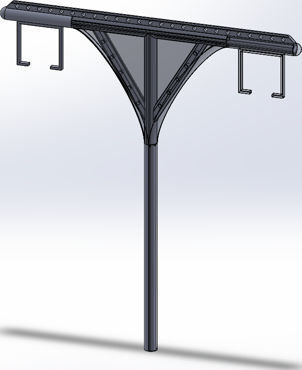
The image below will give and idea what the assembly will look like. The brown parts are the wooden cross beams, the white segments are the pvc pipes covers (which will go over the rest of the wood sections-not just the area shown), the round grey segments are the 3d Printed parts, and the floating parts are Erector parts that will represent the guide way supports (though I still have to design a way to connect it). Likewise, I intend to use other Erector parts to represent I beam that will be how the clamps will connect each other (which will be placed on the clamps' flange holes), but they are more difficult to replicate.

In addition, I contacted Dr. Youssefi to see if he could print out one or two of the clamps as a reference. Fortunately, He managed to manufacture them shortly after.


During spring break, I will make a few of the components (ex. the wooden beams) and further improve on my design (ex. a way to connect the guideway supports). I will also have to consider designing parts to substitute the erector parts if I can't obtain them in time.


Thursday, March 16, 2017

2017/03/15 - Clamping Down on a Design

This week I attempted to finalize the design and dimensions for our architect's model.

Firstly, I decided that we should make our design be 1/12 scale as it the long nature of the structure would make the parts require far too much material.

Then, I made the cross-sectional dimensions of the wooden beams, followed by the dimensions that the attached clamps will have. I also looked into using erector parts which would represent I beams and the modular solar rack base. The basic design is shown below, with the 3d printed and erector parts being highlighted blue. In addition, for large portions, pvc pipes will be used as sleeves to show a smooth look and potentially additional support.


Next was designing the clamp itself. This is one solid part, but as pointed out by a teammate it is too large to be reasonably printed (being over 10 inches long).


Currently, I am redesigning the clamp to be composed of multiple smaller pieces, while still taking advantage of the core idea. Likewise, I will need to find an easy way to attach the guide way.

Wednesday, March 15, 2017

2017/03/08 - Skype around the World

This week, There were two main events:

On Wednesday night, I participated in a skype call with Ron Swenson, Kathlyn Garces, and Andries Louw (who was in South Africa). I shared my documents and designs and we further discussed these and other aspects very thoroughly. Also, Andries showed us a new support structure design, and we intend to see if we can use it.

The other event was an essay for the ME 195 course. The whole prompt was based on the project, and how applying challenges applying it to other countries. Unfortunately, researching and writing for it took up a lot of my time, preventing me from progressing on the project itself.

In addition, I tried seeing if I could refine my project to facilitate production as the maker fair event is coming up soon. This turned out to be more complicated then I expected, so will to discus this further with my groupmates

Wednesday, March 1, 2017

2017/03/01 - The First Spring Presentation


This week, my primary objective was to work on the "Current Status of Design" portion of the presentation. For it I recompiled the different designs our group made through the semester, including the original sketches, the "cat's eye" design, and the sleeve/clamp configuration, and will also talk about the potential solar panels.

In addition, I also made a newer version of the sleeve/clamp design: it uses a "truss clamp" to save weight, an extruded upper segment for the horizontal beam with holes in it that can allow for modular attachments, and cleaner sleeves.

It is also important to mention that I also went to the meeting with Eric Rosenfeld on Saturday. There he explained his research for solar panels (most notably the snap rack system) and we in turn explained our potential designs. We brainstormed about ways to attach the panels, and I suggested using a series of altering cables to hold up the panels, which he seemed to like.

Sleeves.png

2D Outline of Truss Clamp Design

3D Representation of Truss Clamp (with upper guide way beam supports)

Clamp Assembly.png
Semi Translucent Representation of Truss Clamp (with full guide way brackets)


Close up of the Clamp Connection (note the triangular segments to hold adjacent sleeves)